International Resin Modellers Association©SM®TM
SITE UPDATE! As Yahoo! Site Solutions is no longer being updated or maintained after today, Thursday 31 March 2022, IRMA will be moving to a new provider. This will take us some time, so please be patient. We will be listing kit release dates on our new site. Thank you for your patience and understanding.
International Resin Modellers Association ©SM®TM
Zane R Nobbs
405 Old Orchard Drive, 18
Essexville, MI 48732
United States
ph: 001-989-891-1401
fax: 001-989-891-1401
alt: 001-989-465-6241
info
Articles 20:
Building the 1/72 IRMA Kit No. 7©SM®TM Fokker F.26 Phantom

Model and photograph by Zane R Nobbs

Boxart by Zane R Nobbs
Yet another long awaited kit that has finally come to fruition! IRMA received this kit suggestion back in 2009 and initially approached Bob Dros of BEL-AIR MODLES suggesting a resin kit for this very interesting subject. Bob makes a finished model in 1/72 from persplex for sale on his website at www.bel-air-models.com for €1,300. Bob's finished kits are very wonderful and a great value, especially considering all of the work he puts into them.

Photograph used with permission of BEL-AIR MODELS. Photograph by Bob Dros
For those that enjoy the building process, Bob kindly consented to do a master kit for IRMA complete with landing gear! Through several difficulties including two failed attempts at injection molding of resin, the departure of a resin caster and some bad resin, IRMA has finally managed to come out with the kit for the Fokker F.26 Phantom and not just a kit, our kit is hollowed out with a passenger compartment including interior details for seating, clear resin windows, a fully detailed cockpit and optional, opened or closed, entry door, as only Simona can do!

Parts after cleanup. Photograph by Zane R Nobbs
The kit consists of 60 parts in resin, clear resin and metal with a set of decals to make a prototype from the Fokker company. Naturally, as with any resin kit, there is some filing, sanding, filling and buffing to prepare the kit for assembly. It is always best to clean the parts in soapy water to remove any resin release agent. Then examine the kit to make sure all of the parts are present.

Photograph by Zane R Nobbs
A Note About the Engine Nacels.
Some builders have noted that the Rolls-Royce Nene jet engines were centrifuge meaning that the air was pushed to the outer limits of the engine before reaching the fuel, yet in the illustration by Thijs Postma of the Fokker F.26, the engines appear to have two protusions at the front resembling the axials of an axial-flow turbojet. While the centrifuge-flow pushes the air outward before it goes to the fuel, the axial-flow holds the air inward, close to the axial until it reaches the fuel, thus most axial-flow turbojets are much thinner.
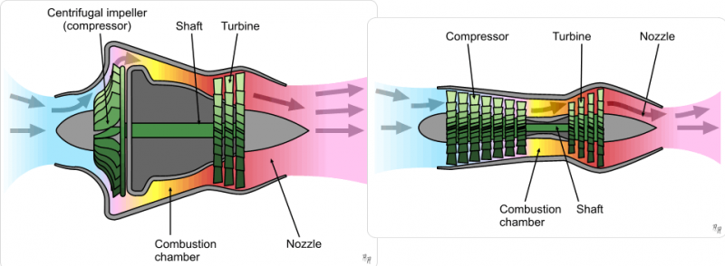
On the right is a centrifuge-flow turbojet and on the left an axial-flow turbojet.
Illustrations from Wikipedia, created by Ermocsopes (retired).
Some hobbyists are recommending to alter Part 39 engine intakes, this is your decision to make, however, Mr. Postma's illustration is correct for the Nene engines. If we look at the French SNCAC NC-1071, a twin engine torpedo bomber for the French Navy from 1948, it has these protrusions from its Nene engines.
SNCAC NC-1071, French Aeronaval Archival photo.
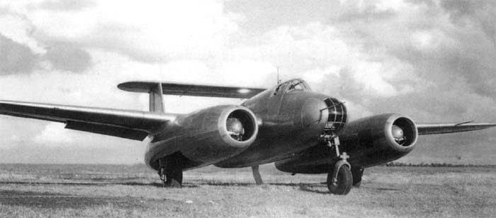
And when we look at the Tupolev Tu-12 of 1947, also powered by Nene engines, it too has similar protusions. The main difference in the protusions is that the Soviet aircraf has 4 braces holding them in place while the French aircraft's are held in place by 3. These protusions were an early form of intake shield to protect the front of the Nene engine which had a much higher intake than previous versions. Rolls-Royce felt that this was a necessary development.

Tupolev Tu-12, Soviet Navy Archival photo.
British aircraft also had the protusions for Nene engines including the Vickers Type 618 Nene Viking of 1948 and Vickers V.663 Tay Viscount of 1950. The Nenes of the Viking are also held in place by 4 braces, which is probably where Tupolev obtained the idea for those of the Tu-12.

Vickers Type 618 Nene Viking, Gettyimages photo.
The protusions of the V.663 Tay Viscount are held in place by 3 braces and although powered by the Rolls-Royce Tay centrifuge (the next advance of the Nene), the protusions remain.
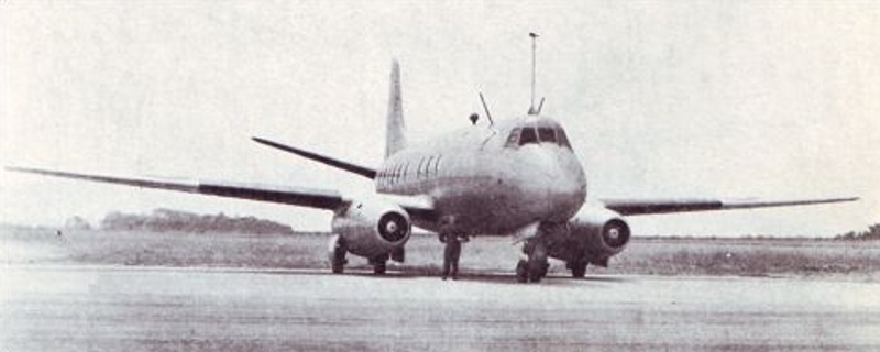
Vickers V.663 Tay Viscount, Vickers Archival photo.
Our recommendation is to leave Part 39 intact as it is based on the illustration by Thijs Postma which is in turn based on the wind tunnel prototype presented at the Paris Air Salon in 1946.

Fokker F.26 Phantom, illustration by Thijs Postma
A Note About the Front Landing Gear Leg
Some have noted that the front landing gear leg (part 57) seems unusually long for the wheelwell. Again as the builder you can modify it as desired. However, some aircraft have had extended front and main gears that reduce then retract. These have come in various forms such as the folding landing gear of the Focke-Wulf Fw-200 Condor of 1937 and the Mikoyan-Grevich MiG-13 of 1945 in which the main landing gear folded almost in half before complete retraction.

Focke-Wulf Fw200 Condor, Lufthansa Archives photograph

Mikoyan-Gurevich MiG-13, MiG Archives photograph
Others use telescoping nose wheels such as the Douglas XBT2D-1 Skypirate prototypes of 1945 to save space for torpedos and bombs, the McDonnell Douglas F-4 Phantom II of 1958 (especially in Royal Navy service) to save space and vary the angle of attack, and the Aérospatiale/BAC Concorde of 1969 for the same reasons.

Douglas XBT2D-1, Douglas Archives photo

McDonnell-Douglas F-4 Phantom II, Royal Navy Archives photo

Aérospatiale/BAC Concorde, Air France Archives photo
So with the advanced thinking of Fokker at that time, innovative ideas such as a telescoping/folding nose wheel would be a very real feasibility. Bob Dros of Bel-Air Models took this into consideration when desiging the master for our kit based on drawings from Fokker.
However, after looking at the drawings intensly, this build will be modified for the typical front landing gear with as minimal modification as needed, basically cutting out between the engine nacells and adding new doors from plastic card and minor front landing gear modification. Much of this insite comes from Robert J Hamann who actually discovered the drawing in the private collection of Wim Vredeling. We are indebted to his research. You can read his article in English at: http://www.hollandaircraft.nl/F81%20Fokker%20F.26.pdf.
IRMA Kit No. 7 Fokker F.26 Phantom - Parts List
1. Nose
2. Cockpit
3. Pilot control column
4. Copilot control column
5. Fuselage/passenger compartment
6. Floor
7. First row center seat
8. First row starboard seat
9. Second row port seat
10. Second row center seat
11. Second row starboard seat
12. Third row port seat
13. Third row center seat
14. Third row starboard seat
15. Fourth row port seat
16. Fourth row center seat
17. Fourth row starboard seat
18. Fifth row port seat
19. Fifth row center seat
20. Fifth row starboard seat
21. Sixth row port seat
22. Sixth row center seat
23. Sixth row starboard seat
24. Entry door (port side)
25. Cockpit canopy
26. First port window
27. Second port window
28. Third port window
29. Fourth port window
30. Fifth port window
31. Sixth port window
32. First starboard window
33. Second starboard window
34 Third starboard window
35. Fourth starboard window
36. Fifth starboard window
37. Sixth starboard window
38. Rest room window (port side)
39. Engines
40. Engine intakes
41. Engine exhaust ring port
42. Engine exhaust ring starboard
43. Tail section
44. Tail plane port
45. Tail plane starboard
46. Tail fin
47. Main wings
48. Landing gear leg port
49. Landing gear leg starboard
50. Main wheel port
51. Main wheel starboard
52. Outer landing gear door port
53. Outer landing gear starboard
54. Inner landing gear door port
55. Inner landing gear starboard
56. Front landing gear door
57. Front landing gear
58. Front landing gear door closed
59. Port landing gear doors closed
60. Starboard landing gear doors closed
61. Decals for prototype
IRMA Kit No. 7 Fokker F.26 Phantom - Assembly
Start by cleaning the parts in warm, soapy water to remove any release agents. Next examine all parts to make sure they look correct. Then start sanding, filing and buffing until all parts are cleaned up. Work very carefully with the clear resin as this is more delicate than the regular stuff. Once parts are cleaned up to satisfaction, begin putting things together.
Some parts will require subassembly and painting before assembly for the cockpit and passenger compartments. Look at the painting guide for these aspects.

Photograph by Zane R Nobbs
Begin by inserting the control colums into the cockpit (part 2) by placing the pilot’s control column (part 3) into the left side and the copilot's control column (part 4) into the right side.

Fokker F.27 Friendship prototype cockpit, photo by Miguel Cano Alva.
Internally the cockpit is a very light blue while the passenger compartment is cobalt blue or possibly dark blue.

Photograph by Zane R Nobbs
Once assembly is complete, paint in a light blue overall with a black console and insert into the nose section (part 1).

Photograph by Zane R Nobbs
Next start the passenger compartment by affixing the passengers seats (parts 7 through 22) into their respective positions to the fuselage floor (part 6). Be sure there is one row of five seats on the port side and six rows of seats down the center and on the starboard side. When completed, paint cobalt or dark blue and insert into fuselage (part 5).

Fokker F.XXXVI passenger compartment, Smithsonian Institution.
Passenger seats are a cobalt blue with white covers or orange/red in a pre-war type style. The floor too can be blue of a darker shade. If you choose to include Fokker personnel, their uniforms are a dark blue.
Passengers would be wearing the colors of the day, typically bright and happy colors for the Dutch.
 Photograph by Zane R Nobbs
If you're going to put in crew and passengers, now is the time, before continuing on. After they are inserted into the cockpit (part 1) and fuselage (part 5) then you can proceed. If you want to include the restroom, sinks and toilets can be found on shapeways*.

Photograph by Zane R Nobbs

Photograph by Zane R Nobbs
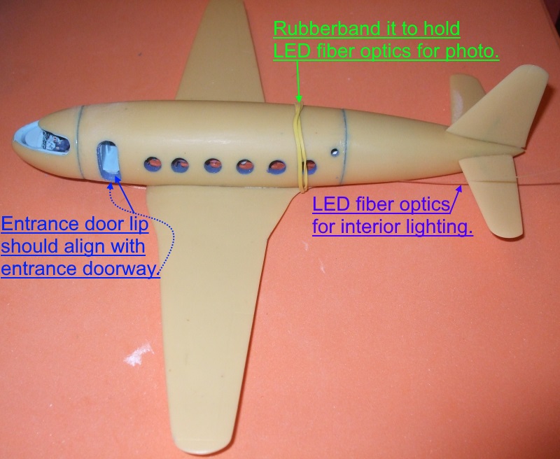
Should you with to install interior lighting, fiber-optic LEDs work well. For this a single strand, notched for each row of passengers, with lighting for the restroom, entrance and navigator's office works well. Make sure you leave enough to reach down a landing gear leg for the power source. When inserting the passenger deck, be sure to start at the rear of the fuselage because that opening is larger than the front. Aircraft entrance door lip should align with the door opening.

Photograph by Zane R Nobbs
For the cockpit, a single notch can suffice to brighten it up as an overhead lamp. Not sure about lighting the instrument panel yet.

Photograph by Zane R Nobbs
For the tail section (part 43) fasten port tail plane (part 44) to the left followed by the starboard tail plane (part 45) to the right and the tail fin (part 46) to the top. Next join the cockpit (part 1) to the fuselage (part 5) to the tail (part 43).
Photograph by Zane R Nobbs
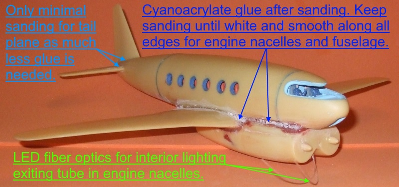
Prior to joining the cockpit to the fuselage, to install the interior lighting, be sure to insert about 8 mm of 3 mm tubing for the LED fiber optic strings to exit down to the engine nacelles to meet the next section of rod for the power source.

Photograph by Zane R Nobbs
To add ballast for a balanced model the engine box can be hollowed out. When measuring the amount needed fore of the center of gravity, it will balance a 2.2 oz., however, just to be sure, in this case hollowing out as much as possible seemed the best option. If using a dremel, do NOT use the grey/blue bits, two of these disintigrated during the process. Instead, use the red bits to make the initial boxes and the metal bit to even everything out. Be careful of the drill torque, as in this case the starboard engine nacelle was almost destroyed! In the future we will hollow out the engine box for your convenience.
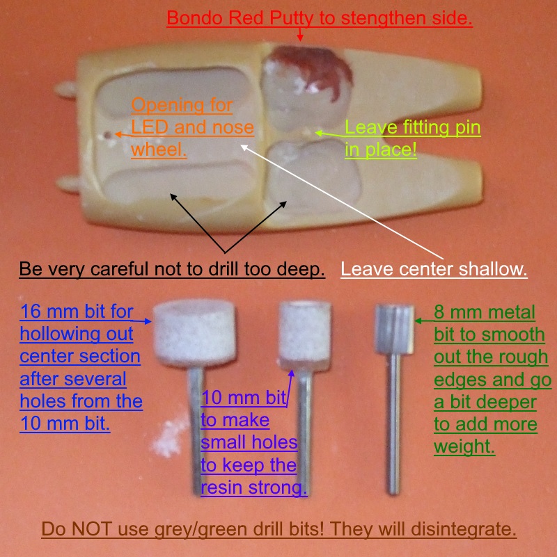
Photograph by Zane R Nobbs
When gluing the weights in, be sure to use white glue in case some adjustments are needed. In this case an opening had to be left to run the LED fiber optics through as well as installation of the front landing gear leg. More on that later.

Photograph by Zane R Nobbs
Now attach the engine intakes (part 40) to the engines (part 39) and the port exhaust ring (part 41) to the left engine outlet and the starboard exhaust ring (part 42) to the right engine exhaust. Then attach the main wings (part 47) to the fuselage (part 5) and underneath this fasten the main engines (part 39).
Photograph by Zane R Nobbs
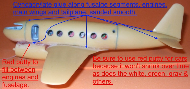
Be sure to use red putty (for automobiles) to cover the weight in the engine nacelles as the engines are joined to the fuselage. Once dried, cover all seams with a cynoacrylate glue. In the photo the glue shows white after sanding. This is also a good way to gauge if more is needed for an even better touch of realism. Use as much as necessary then sand it all down with sand paper or a round file for resin or plastic.
Photograph by Zane R Nobbs
For extended landing gear glue port main landing gear leg (part 48) to the left landing gear opening underneath the main wing (part 47) and the starboard main landing gear leg (part 49) to the right landing gear opening. Next place the port main wheel (part 50) onto the landing gear leg (part 48) and the starboard main wheel (part 51) to the right landing gear let (part 49). Place the port outer main landing gear door (part 52) onto the port landing gear leg (part 48) followed by the starboard outer main landing gear door (part 53) to the starboard main landing gear let (part 49). Then attach port inner main landing gear door (part 52) to the inner left main landing gear opening and the starboard inner main landing gear door to the right main lending gear opening. Note: Even with replacement legs for main landing gear, this segment of building stays the same, save for adding the axles for the main wheels.

Photograph by Zae R Nobbs
Moving to the front, fasten the front landing gear (part 57) to the front landing gear opening in the nose section (part 1) and the front landing gear door (part 56) to the main landing gear leg (part 57). Note: For this build, since moving the front landing gear to a new position, directions will be a bit different. See photo below.
Photograph by Zane R Nobbs
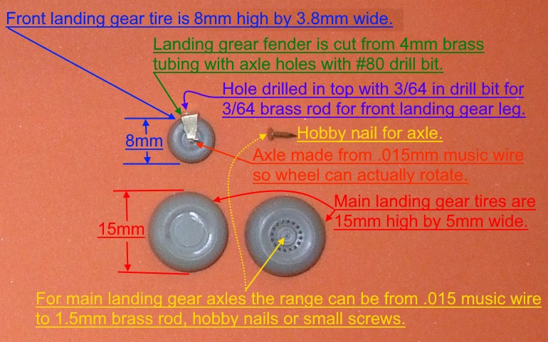
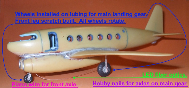
To make more authentic looking landing gear, based on the recent drawing, an 8mm x 3.8mm front wheel appears to be more in keeping with the Fokker war-time and post-war projects. The front landing gear fender is based on the post-war Fokker F.27 Friendship, but scaled upward as in the war-time Fokker F.24 proposal. To make the front fender a 4mm brass square tubing was used. Each angle was cut with a Dremmel metal cutting blade down each side, then extended by cutting the lower part of the square down the middle and bending it outward with a pair of pliers. This was follwed by drilling a 3/64 inch hole in the top to receive a 3/64 brass rod for the front landing gear leg. Next the wheel was lined up with the ends of the fender and drilled through with a #80 drill bit to receive a .015mm music wire axle. This leaves enough clearance for the wheel to rotate. The curves on each side of the fender were achieved by grinding down with the Dremmel bit. This also removes any sharp edges.
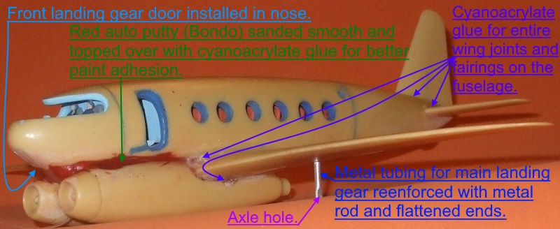
Photograph by Zane R Nobbs
For the main landing gear 3/64 tubing was used, flattened at the ends with pliers which leaves enough room for a variation in axle size from .015mm music wire to 1.8mm rod, hobby nails or small screws. Tubing can also be left hollow with appropriate axle sizes. These wheels too can rotate if desired. Another result of moving the front leg is that the nose opening will no longer be necessary, so the front landing gear door (part 58) can be inserted into the nose.
Photograph by Zane R Nobbs
If you prefer the landing gear up, then insert the front landing gear door (part 58) into the nose landing gear opening, the port landing gear doors (part 59) into the left main landing gear opening and the starboard landing gear doors (part 60) into the right main landing gear opening.
Photograph by Zane R Nobbs
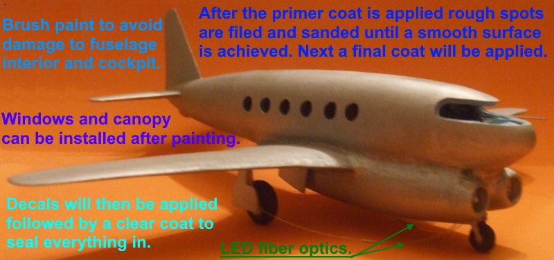
Upon completion of painting the exterior of your F.26, place the cockpit canopy (part 25) into the nose section (part 1) and the passenger windows (parts 26 - 37) into the relevant openings (parts 26-31 on the port side and parts 32-37 on the starboard side) followed by the rest room window (part 38) into the opening on the port side of the fuselage.
Model and photograph by Zane R Nobbs
If you fuselage windows look like they're inside when you look at them from an angle, then they are correct! With the blue rims there will be an illusion that they're distorted, however, theyre not.
Model and photograph by Zane R Nobbs
Lastly, place the decals as per the drawings supplied in the kit.

Model and photograph by Zane R Nobbs
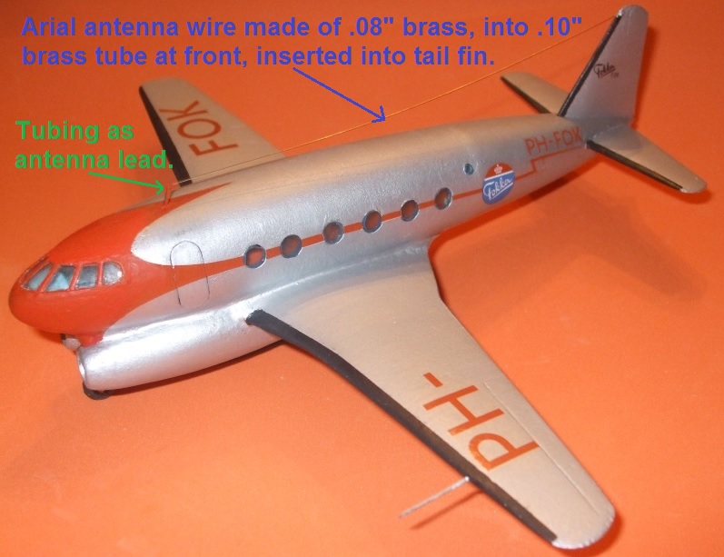
You can also add a pitot tube and antenna wire based on the illustrations on the web site.

Model and photograph by Zane R Nobbs
IRMA Kit No. 7 Fokker F.26 Phantom - Painting
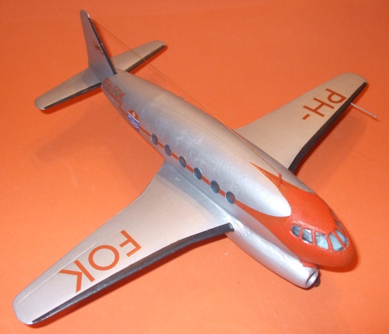
Utilizing the typical postwar color schemes for commercial aircraft, this kit has decals for a Fokker prototype as it would appear prior to entering service for KLM or any other airline in their livery. For our example the overall fuselage is flat aluminum with a rot (red) RLM 23 cheat line and front.

Model and photograph by Zane R Nobbs
A 1950 secario would be where the top portion is flat white down to the windows where the "cheat line" up to the front of the aircraft would be a flat orange/red. Everything below is flat aluminum. The tires are rubber with silver centers and internal portions of the landing gear bays are also flat aluminum.

Model and photograph by Zane R Nobbs
De-icer boots on the front of the main wings, tail planes and tail fin are all black with burnt metal for the jet exhausts.

Fokker F.26 Phantom with extended nose landing gear leg. Illustration by Zane R Nobbs and Copyrighted © by IRMA (and watermarked).

Here is the kit built as the extended nose wheel version by IRMA Member Armando Gill and his friend Leonardo Carrillo. This livery would be in the 1950s.
Model and photograph by Armando Gill and Leonardo Carrillo.

Fokker F.26 Phantom with under nacelle nose landing gear leg. Illustration by Zane R Nobbs and Copyrighted © by IRMA (and watermarked).
This kit is completed as the aircraft would have looked in the late 1940s. The Fokker logo on the fuselage is an added touch based on a style used on the Fokker F.27 Friendship, the next aircraft in the Fokker commercial transport liine.

Model and photograph by Zane R Nobbs
![]()
ONTWERP 232 from the Fokker Heritage Trust (Fokker watermark added)
Decals placement will have the code numbers in orange on the top of the wings while the dark go underneath. For the tail fin the black Fokker logo can be used if pursuing the Thijs Postma color layout, or we have also included the Fokker logo in orange and blue which can be placed on the tail, the rear fuselage or front fuselage as this varied on different prototypes. It is also recommended to paint around the edge of the passenger windows before placing them in their respective openings for more realism.

Model and photograph by Zane R Nobbs
In this build example the fueling cable is actually the LED fiber optics to the Dutch Petroleum Shell truck housing the switch and power for the internal lighting.
And now your Fokker F.26 Phantom is cleared for takeoff!
International Resin Modellers Association ©SM®TM
Zane R Nobbs
405 Old Orchard Drive, 18
Essexville, MI 48732
United States
ph: 001-989-891-1401
fax: 001-989-891-1401
alt: 001-989-465-6241
info