International Resin Modellers Association©SM®TM
SITE UPDATE! As Yahoo! Site Solutions is no longer being updated or maintained after today, Thursday 31 March 2022, IRMA will be moving to a new provider. This will take us some time, so please be patient. We will be listing kit release dates on our new site. Thank you for your patience and understanding.
International Resin Modellers Association ©SM®TM
Zane R Nobbs
405 Old Orchard Drive, 18
Essexville, MI 48732
United States
ph: 001-989-891-1401
fax: 001-989-891-1401
alt: 001-989-465-6241
info
Articles 12
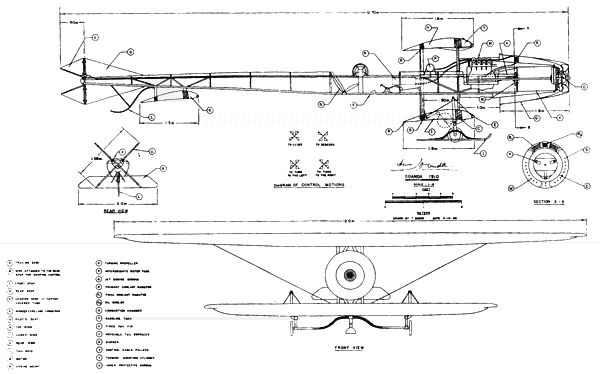
Building the 1/72 IRMA Kit No. 3©SM®TM Coandă-1910
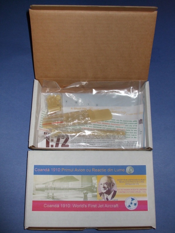
As is typical, when you receive your Coandă-1910 you will get the standard IRMA box which contains the resin kit with photo-etched and metal detail parts, a history of the aircraft, color instructions, a Certificate of Authenticity and disclaimer. This kit has no decals because this aircraft had no markings.

A real benefit with this kit is that the molding is so well done, no cleanup is necessary! And the detail is amazing, right down to the rivets, panels and cockpit details! Good job FanKit!
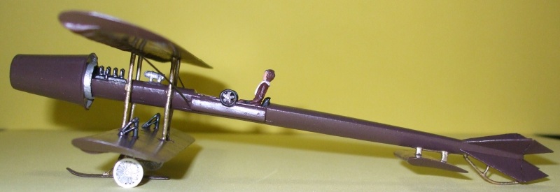
Upon opening the plastic bags the builder is presented with 28 parts-20 resin, 6 metal details (landing gear springs and wire for cables) and two photo-etched ducted-fan blades. There is also some copper wire for those that wish to add more detail.

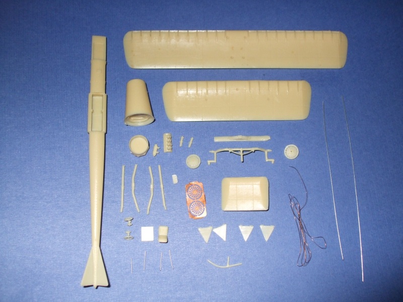
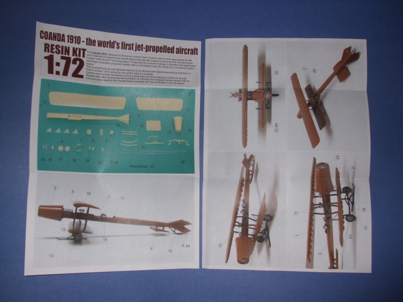
Well, now, when it comes to building this kit, it is a bit different from those we have produced in the past. Unlike building the jet aircraft from the post-WWII era, the Coandă-1910 is what we call a "sesquiplane" meaning a bi-plane with the lower wing smaller than the upper. This is held in place by four struts fastened to the fuselage.

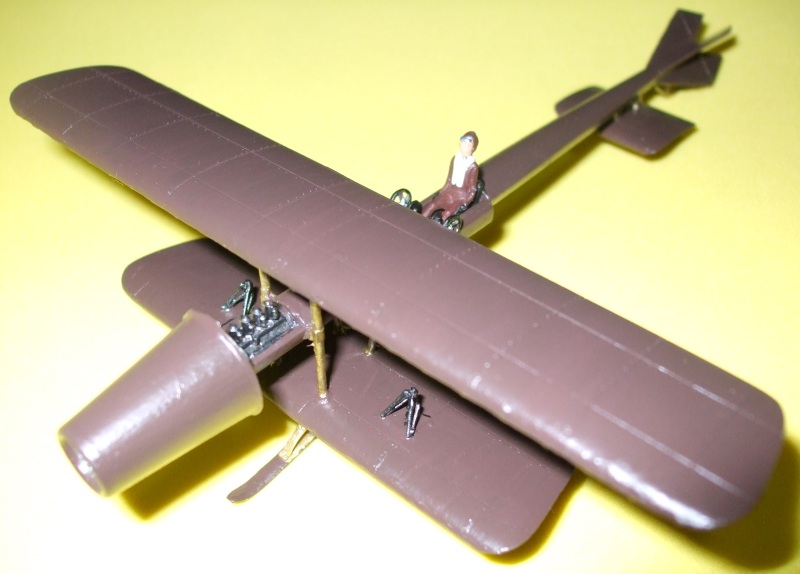
When building this kit its best to start with the cockpit details. First you will need the fuselage (piece #3) as the basis. Put the seat in place (piece #9) then the cover at the front of the cockpit (piece #7), putting the instrument gauge panel (piece #20) in the middle. Next place the wing-warping control wheels (pieces #19 x 2) on each side of the cockpit matching the colums on either side.
At the front of the fuselage go the engine parts. Place the cylinders of the Clerget piston-engine (piece #8) inside the rectangular depression at the front. Also at this time the auxiliary fuel tank (piece #16) can be placed in front of the cockpit, over the small retangular rise. Be sure the point is facing the front of the fuselage. Now put the exhaust funnel (piece #18) on the Coandă Air Reactive Unit (piece #5) then place the front of the fuselage inside the funnel, matching the triangular depression in the funnel.
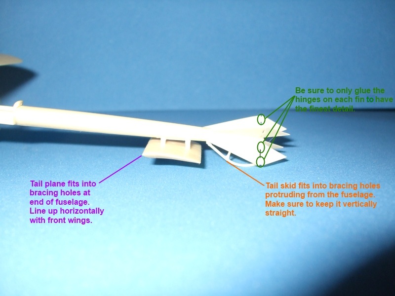
Moving to the rear of the fuselage, take the control surfaces (pieces #6 x 4) on each of the tail-fins. Be sure to match the hinged edges to the fins! We'll return to this part later.
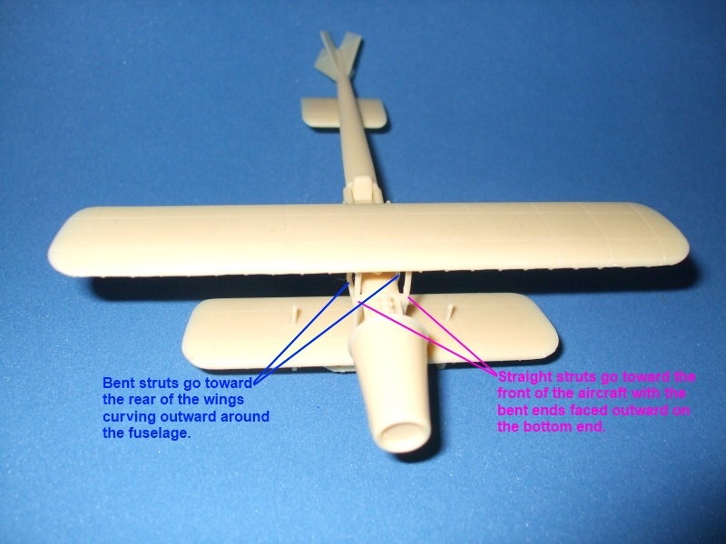
Next take the lower wing (piece #2) and turn it face-down. Locate the three holes in the lower surface and match these with the landing gear brace (piece #14). Once completed, turn the wing over and locate the outer holes on the upper surface. In these place the landing gear spring braces (pieces #15 x 2) one on each side.
Now for a rather difficult portion. Locate the four inner holes and match two rear struts (pieces #11 x 2) making sure that the fuselage clamp is on the slightly higher half. These should bend outward, around the fuselage. Try to match them to the landing gear braces vertically then horizontally. This will take some time, patience and extreme accuracy. Now match the two front struts (pieces #10 x 2) with the bent ends on the bottom and facing outward. Again, match to the back struts vertically and horizontally.
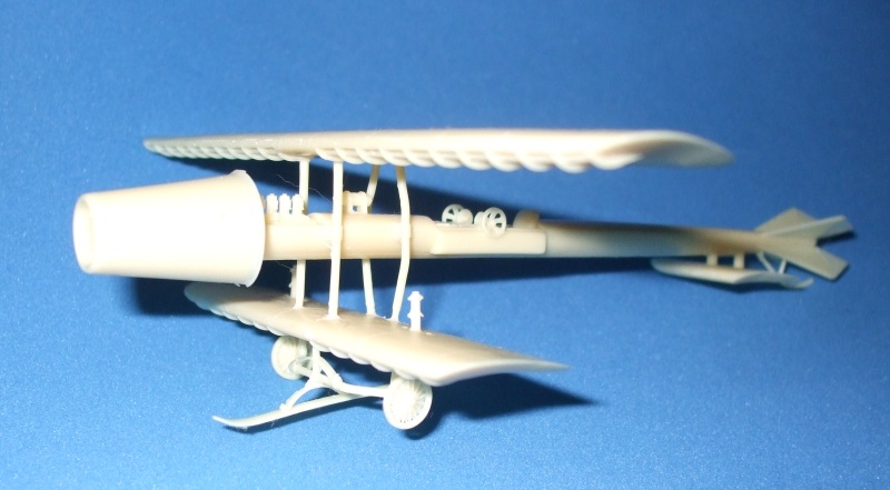
This point is the make or break part of the build. Very carefully place the fuselage inside the four struts maching the four protusions on each side to the holding clamps on the struts. To buy some time you can use a super-glue gel with a small dab on each rise on the fuselage. Once matched up, try to balance the fuselage on a couple of paint bottles or stack of cards to keep things level horizontally and straight vertically. Let things dry and the re-enforce with a liquid super-glue. Again, let it dry thoroughly, at least an hour just to make sure.

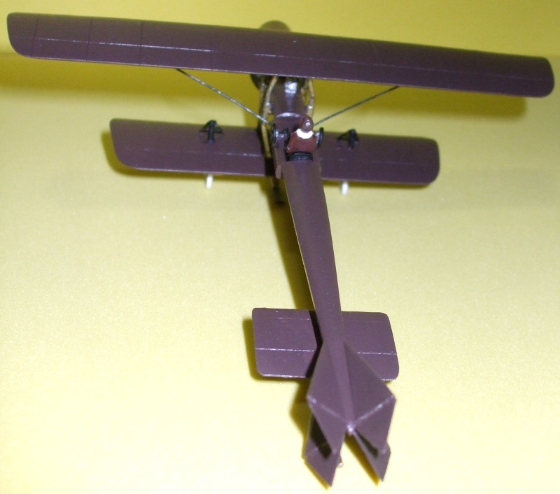
Take the upper wing (piece #1) and place it upside down. Match the four struts to the four holes on the lower surface, wide holes and the front, narrow holes at the back. Leave in this position and place something under the tail to keep it level with the front wing. Place the rear wing (piece #4) on the rear fuselage with the ends outside of the protrusion on the lower side. Locate the landing skid (piece #12) to the holes in the extensions on the tail.
Once dried, dry fit the wheels (pieces #17 x 2) on each side of the landing gear bracing. Don't glue them in place until they are painted! With the wheels on, place the anti-tip skid (piece #13) in the middle of the landing gear bracing. This will complete the resin portion of the build.

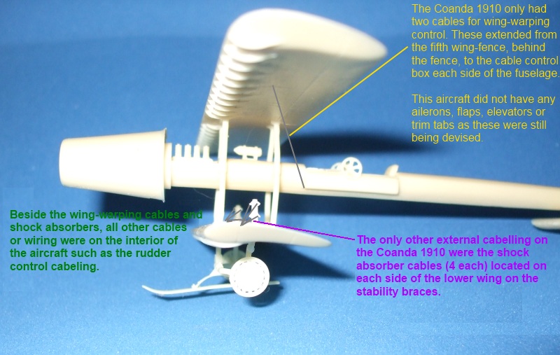
Depending on whether you wish to paint the kit at this point or place the wiring first will determine the next build portion. To continue with the build, take the landing spring wires (pieces #21 x 4) and either place one on each side of the spring braces (pieces #15) on each side or cut at the 2/3 part and place two on each side of each brace. This depends on how much detail you wish to have. After this, measure and cut each control cable (pieces #22) and locate under each side of the upper wing, about 1/4 the from each end at the fifth wing fence from the inside and just behind, and bring down toward the underside of the boxes below the control wheels on either side of the fuselage.
In regard to the wing-fences on the lower surfaces, those on the upper-wing had wide air inlets and did pass through to the top with a reduced opening. This was a stability factor in the wing-warping technology by Mr. Coandă. In the kit it was considered these would be to small to be noticable, however, if superdetailing is desired, these can be cut all the way through or from the top. Be sure that they are individual openings and do not overlap the wing-fences below!
Also for the "rudders" be sure that the openings between the hinges remain. There were only two hinges per fin. These worked in opposing pairs for steering. Again, this was unique to the technology of Mr. Coandă and cabel controls for the tail were all internal.
For the photo-etch, cut out one of the fan blades (piece #23) and insert it into the front of the Coandă Air Reactive Unit. Prior to this it should be painted flat aluminum or flat silver. The copper wire enclosed can be used to enhance the amount of detail you desire such as wrapping for the springs, interior cockpit detail for the control wheels or additional bracing wire.

Moving on to the painting portion, the colors required will be mahogany (such as Gunze Sangyo #H84) for the over all finish since the original was a "mahogany veneer" in color. To bring out the wood grain a dry brush of either deck tan (Tamiya #XF-55), rough sand (Gunze Sangyo H346), or buff (Tamiya XF-57). The interior of the control wheels, landing gear wheels, auxiliary fuel tank and engine fan will be flat aluminum or flat silver. Pilot's seat, outer side of the controls wheels, engine block and instrument panel will be flat black. Tires should be flat white since cobalt black was not added to rubber until after 1913. Braces, landing gear bracing, tail skid and struts can be painted flat brown, flat black, or even brass or copper as this is unknown for the original. Control cables would most likely be either flat black or perhaps a dark metallic color. Engine cylinders could be flat aluminum, burnt metal or gunmetal.

For painting acrylic paints by either Tamiya or Gunze Sangyo seem to work best on resin. Typically it takes about three coats. For the base coat of mahogany paint front to back the first coat. Next paint cross ways, this eliminates brush lines. For the third, and hopefully final coat, again go front to back. This adds fine lines from the wing sweeping over the surfaces. To add the wood grain take a wide brush with just a touch of the lighter color, and lightly drybrush over the mahogany making sure not to lift the brush on each sweep! Wood grain is continuous and if the brush is lifted, continuity will be lost.

From available illustrations from the period it appears that brass was the most likely finish for the struts, braces and landing gear. Gunmetal (Tamiya) was used for cables and landing gear springs.

Then paint the fine details using the colors mentioned above. Most of all, be patient, take your time for better accuracy and when you are done you should have a fine model of the world's first built jet (motor-jet) aircraft!
You can get your 1/72 IRMA Kit No. 3 Coandă-1910 from IRMA for $60 for IRMA Members + shipping or $70 for non-members + shipping.
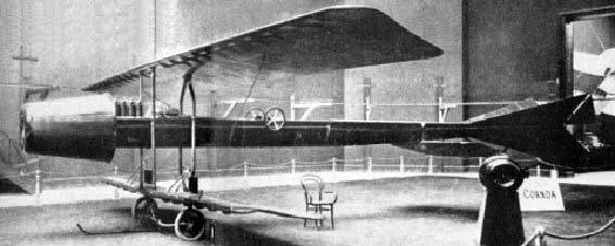
IRMA would like to thank Count Caproni, from the Delta 2 1/72 Campini-Caproni CC.2 kit for sitting in as Dr. Coandă for this photo session.
- Zane R Nobbs, copyright International Resin Modellers Association 2010
International Resin Modellers Association ©SM®TM
Zane R Nobbs
405 Old Orchard Drive, 18
Essexville, MI 48732
United States
ph: 001-989-891-1401
fax: 001-989-891-1401
alt: 001-989-465-6241
info